Immagini e screenshot possono differire dalla versione corrente a causa di aggiornamenti dell'ambiente di development..
¶ 1. Componenti e concetti base
IEC Editor è un tool di programmazione PLC corrispondente allo standard IEC 61131-3. Supporta la programmazione standard ST, IL, LD.
Il codice può essere avviato in modalità Simulazione o installato sul PLC desiderato.
¶ 2. Project
Il progetto contiene gli oggetti POU che costituiscono un programma PLC e la configurazione necessaria per avviare specifici sistemi (PLCs, dispositivi).

Gli oggetti POU sono gestiti nella finestra di modifica POUs.
Oggetti di risorsa specifici del dispositivo sono gestiti nell'Hardware view.
Il progetto è salvato nella cartella <INSTALL_FOLDER>\nwsirius_IEC\applicat\<PROJECT_NAME> e la struttura POU è salvata in un file XML chimato <PROJECT_NAME>.XML. Il formato XML corrisponde agli standard PLCOPEN XML.
La configurazione delle task di progetto può essere fatta nel nodo Configurations del project tree.
¶ Template
Il template di un nuovo progetto coniste in una parte di configurazione a un POU Main in forma di testo strutturato, Il template di progetto non contiene hardware.
¶ Impostazioni
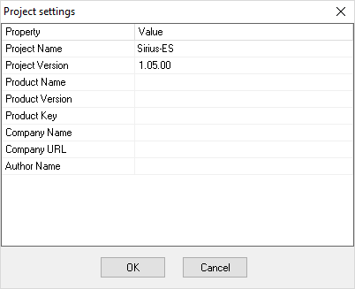
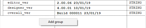
Le impostazioni del progetto sono il primo nodo del project tree. Il dialogo delle Impostazioni di progetto può essere usato per modificare o visualizzare informazioni specifiche del progetto come nome dell'autore, versione, ecc...
¶ Importazione
Parte di altri progetti può essere importata dal file menu Import... . L'utente può selezionare quale parte dell'altro progetto da aggiungere a quello corrente. La funzione import funziona con i file XML standard PLCOPEN XML.
¶ Linguaggi di programmazione supportati
I linguaggi di programmazione supportati da IEC Editor sono menzionati nell'IEC standard IEC 61131-3:
- LD editor per Ladder Logic Diagram (LD)
- IL editor per Instruction List (IL)
- ST editor per Structured Text
¶ POU, Program Organization Unit
Il termine POU è usato fondamentalmente per tutti gli oggetti che sono usati per creare un programma PLC.
POU é la Program Organization Unit di tipo Program, Function o Function block.
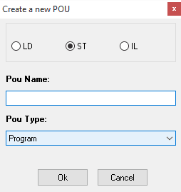
Per aggiungere un POU seleziona una voce appropriata nel Project tree (per esempio il Program Node), premi il tasto destro e usa il comando New program dal menu contestuale.
Il dialogo Create a new POU verrà aperto, dove potrai configurare nome, tipo e linguaggio di implementazione del POU. Nota che il tipo di POU può essere cambiato dalla casella combinata POU type.
¶ Variabili
Le variabili posso essere definite per ogni tipo di POU. Le variabili possono essere LOCAL, TEMP e INPUT, OUTPUT, IN_OUT per funzioni e function blocks.
Le variabili locali posso essere definite come NORMAL, RETAIN, CONSTANT. I tipi di variabili possono essere elementari, data type definiti dall'utente o arrays.
¶ Data types
Oltre a quelli standard, l'utente può definire i propri data types.
I data types possono essere aggiunti al progetto dal comando Add data type. Premendo il tasto destro sul nodo Data types nel project tree. Il data type editor apparirà e l'oggetto può essere configurato.
¶ Variabili globali
Le variabili globali sono variabili visibili dall'intero progetto. Sono definite nella sezione del progetto Configuration.
Le variabili globali posso essere normali, RETAIN o CONSTANT. L'hardware è automaticamente incluso tra le variabili globali ma non sono mostrate nel variable panel, in modo da separare le variabili globali definite dall'utente da quelle hardware.
L'array delle variabili globali non può essere definito. L'array dev'essere incapsulato in un data type, in questa impostazione possono essere usati come var esterne nei POUs.
¶ Hardware Tree and devices
Nella pagina Hardware (Sirius PLC hardware tree) puoi mappare l'hardware sul quale l'applicazione è stata avviata.
Il root node del tree è sempre un dummy node chiamato Sirius PLC che rappresenta il PLC. Quando un viene creato un progetto è presente solo questo e tre sub-nodes (hardware groups).
I nomi degli oggetti hardware sono modificabili qui, premi il tasto destro su node sotto groups o premi il pulsante F2 dopo aver selezionato il node. Doppio click sul node per aprire la tab Hardware nella pagina principale.
¶ Configuration
Configuration è la sezione del progetto dove le tasks e le loro istanze sono definite.
Double click su Configuration per aprire la pagina di configurazione.
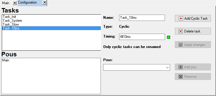
La pagina permette agli utenti di creare e configurare task definitions e aggiungervi POUs. Le task Init, System and Slow sono create di defaul e non possono essere cancellate.
Per creare una nuova Task premi il pulsante Add cyclic task , poi configuralo.
Per aggiungere POUs alle task, seleziona una task, seleziona un POU dal “POUs” combo, poi premi Add.
Per rimuovere un POU, seleziona il POU dalla lista e premi Remove.
Usa move up o move down per cambiare l'ordine di esecuzione dei POUs.
Valori dal bus (ie: canopen) sono impostati nel System Task (2 ms). Se i valori sono usati in una task da 10 ms possono essere modificati. Per usare un valore stabile, salva il campo in una variabile all'inizio del POU, poi utilizzalo.
¶ 3. Interfaccia editor
Interfaccia utente editor è organizzata in cinque sezioni principali; possono essere ridimensionate in altezza e larghezza, ma non mosse o nascoste.
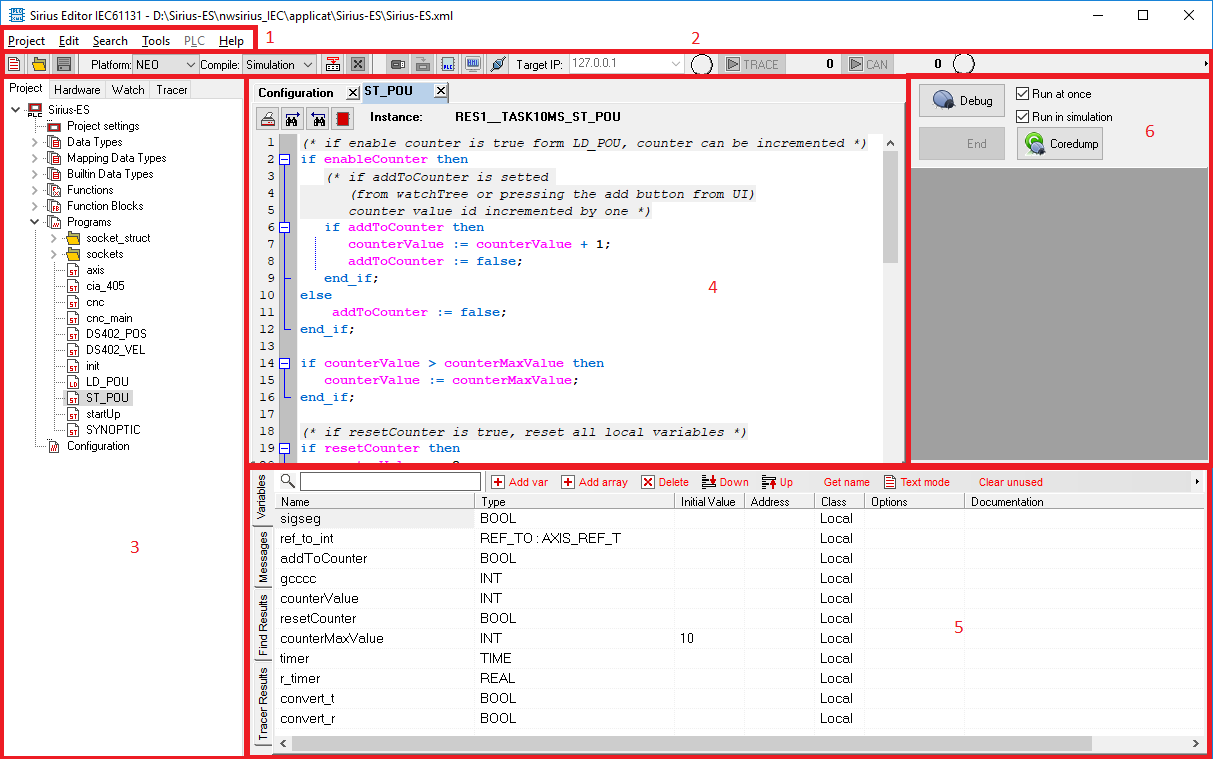
The editor components are listed below:
| Section | Name | Description |
|---|---|---|
| 1 | Barra menù | Fornisce un menu per gestire progetti, modificare fonti e trovare testo. |
| 2 | Barra tools | Contiene i pulsanti tools per il project life cycle management, da New Project a Install sul dispositivo desiderato. |
| 3 | Pannello strutture | Qui è possibile vede la struttura del progetto, struttura hardware e la watch list per il debugging. |
| 4 | Pannello edit | Contiene un foglio tab per modificare il codice sorgente. |
| 5 | Pannello footer | Variabili, messaggi e risultati delle ricerche si trovano in questo pannello. |
| 6 | Debug panel | Debug del progetto su plc o simulazione. |
¶ Barra menù
Nei prossimi capitoli vedrai una panoramica della strutta dei menù principali e comandi contenuti nella barra menù.

¶ Menù di progetto
Contiene i comandi per le gestioni dei progetti.
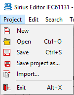
| New | Crea un nuovo progetto. Una finestra pop-up appare dove scegliere il nome del progetto. Una cartella chiamata project name viene creata. Dentro la cartella sono posizioni i file di progetto. Il codice sorgente del progetto è scritto in un file project name.xml.Questo è un file standard PLCOPEN XML. La directory del progetto è posizionata in <INSTALL_FOLDER>\nwsirius_IEC\applicat\.Il progetto può essere in un singolo file xml o molteplici, uno per ogni POU.. Molteplici file sono semplici da unire, se ci lavorano diversi developer. |
| Open | Apre un progetto salvato. Il codice sorgente e la configurazione hardware vengono caricate. Per caricare il progetto fai doppio click sul file di progetto xml principale. |
| Save | Salva il progetto corrente nella cartella di progetto. Questo comando salva il codice sorgente nel file project name.XML. Se la modalitò "expand project" è attiva, il progetto viene divisono in diversi file, uno per POU. Per salvare il progetto in un singolo file, usa la modalità "PLC Open project". |
| Save project as... | Crea una copia del progetto corrente. Un pop-up apparirà dove scegliere il nome del progetto. Tutti i file di progetto verrano salvati nella nuova cartella e il file di progetto principale verrà rinominato con il nuovo nome del progetto. |
| Import | Importa parte del progetto (POUs) da altri file in formato PLCOPEN XML, il pop-up mostra le parti del progetto scelto, possono essere importate spuntandole. Se sono presenti variabili globali, la relativa checkbox apparirà. Spuntandole, tutte le variabili globali del progetto selezionato verrano importate nel progetto corrente. |
| Exit | Se vengono fatte modifiche, un pop-up ti informerà per scegliere di salvarle o meno. |
¶ Menù Edit
Contiene comandi per operazioni di editing.
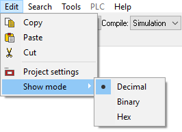
| Copy | Copia il codice sorgente selezionato negli appunti |
| Paste | Incolla dagli appunti |
| Cut | Copia negli appunti e rimuovi il codice sorgente dal luogo di origine. |
| Project Settings | Come il doppio click su Project Settings nel project tree, apre le finestre di impostazioni del progetto. |
| Show mode | Imposta il tipo di visualizzazione dei dati nella watch tab, i dati posso essere mostrati come decimali, binari o hex. |
¶ Menù Search
Contiene comandi per trovare e sostituire codice sorgente.
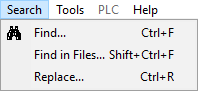
| Find... | Permette di trovare testo all'interno del codice sorgente. Dalla finestra "Find" puoi inserire il testo da trovare e specificare se cercare solo nel documento corrente o nell'intero progetto. I parametri Case Sensitive e Whole Word possono essere impostati per filtrare la ricerca. I casi di corrispondenza sono listati nella tab Find Results. Premendo il tasto F3 o cliccando sui risultati, il risultato specificato viene evidenziato. |
| Find in FIles... | Apre lo stesso pop-up del comando Find, ma con look in impostato a "Entire project". |
| Replace... | Il testo specificato sarà rimpiazzato con altro. I parametri Case Sensitive e Whole Word possono essere impostati per filtrare la ricerca. Il prompt ti permette di accettare sostituzioni correnti, sostituire tutto o coancellare l'operazione di sostituzione. Se Entire Project è spuntato, il prompt su Replace non è disponibile. |
¶ Menù Tools
Tools per gestire progetti e PLC.
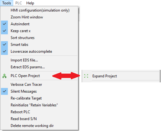
| HMI configuration (solo per simulazione) | Apri la finestra di configurazione HMI. L'utente può impostare l'interfacia utente (.UI files) selezionandola con "Open file" e le dimensioni dello schermo. Questi campi devono essere riempiti per avviare l'interfaccia HMI. |
| Finestra Zoom Hint | Quando la finestra Hint viene mostrata nel text editor, l'utente può espandere la finestra e vederlo da remoto (se il PLC non si trova vicino al PC). |
| Import eds file | Ti permette di importare un file eds nel repository, per la configurazioni di Can Nodes.. Seleziona un file eds dal disco, poi premi il pulsante "Open". Una casella di messaggio apparirà se l'operazione ha avuto successo. |
| AutoIndent | Abilita / disabilita la rientranza text editor. Riapri l'editor form per fare effetto. |
| Keep caret X | Enable / Abilita / disabilita la posizione caret x keep del text editor, usata per muovere il cursore tra le righe in diverse modalità. |
| Sort structures | Riordina i campi della watch list e l'hardware in modo ascendente. |
| Smart tabs | Usa il tasto tab in modo simile allo spazio, (1 step) |
| Extract EDS parameters | Permette all'utente di scegliere un fiel EDS importato precedentemente e estrarvi la lista di parametri all'interno del gruppo "Manufacturer object". |
| Expand project / PLC Open project | Usato per selezionare il metodo di salvataggio del progetto. Usa la modalità Expand per salvare il progetto in molteplici file XML (uno per POU). Usa la modalità PLC Open per salvare il progetto in un file XML standard (PLC Open standard). |
| Verbose Can Tracer | Aggiunge più informazioni circa TX/RX nel Can Tracer |
| Silent Messages | Riduce il numero di messaggi di errore del PLC mostrati nella tab messaggi. Quando l'editor IEC chiede qualcosa al PLC, alcuni messaggi (e errori) vengono mostrati in finestre pop-up. Per disabilitare i pop-up, spunta silent messages: tutti i messagi verranno scritti nella message tab invece che nei pop-up. |
| Re-calibrate target | Lancia il programma di calibrazione del touch-screen sull'indirizzo ip selezionato. |
| Reinitialize "Retain Variables" | Resetta le variabili Retain dell'indirizzo IP selezionato. |
| Reboot PLC | Invia il comando "reboot" all'indirizzo IP selezionato. |
| Read board S/N | Legge il numero seriale della scheda del PLC con l'indirizzo IP selezionato. |
| Delete remote working dir | Se il PLC risponde all'indirizzo IP selezionato tutto il contenuto della directory PLC (/SiriusApplicat) verrà cancellato. |
¶ Menù PLC
Questo menù è abilitato sono quando si è connessi al PLC (fisico o simulazione).
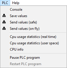
| Console | Usato per mandare comani LINUX al PLC. I comandi devono essere terminati da sè stessi perchè non possono essere soppressi (come TOP). L'output dei comandi viene mostrato nella tab messaggi. Nell'esempio "LS /SiriusApplicat" il comando viene inviato alla simulazione e il risultato è l'LS della cartella di progetto. |
| Save values | Salva tutti i valori delle variabili usate dal PLC. Un modulo "save as" permette all'utente di scegliere il file di destinazione. Crea un file di testo con VAR_NAME VAR_VALUE |
| Send values (safe) | Carica da un file i valori delle variabili e le invia al PLC dopo averlo messo in pausa. Dopo questa operazione il PLC verrà riavviato. |
| Send value (on fly) | Invia i valori del PLC senza metterlo in pausa. Da usare con un numero limitato di variabili. |
| Cpu usage statistics (Real time) | Monitora l'uso della CPU mentre si è connessi al PLC (no simulazione). |
| Cpu usage statistics (User space) | Monitora il processi eseguito sul PLC nello user space. |
| Cpu Info | Mostra informazioni circa la CPU |
| Pause PLC program | Mette in pausa l'esecuzione della tasks del programma IEC. Il PLC è in funzionamento ma le tasks IEC non verrano eseguite. |
| Restart PLC program | Le tasks IEC vengono avviate nuovamente. |
¶ Menù Help
Comandi per ricevere aiuto e informazioni on line.
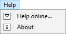
| Help online... | Link a questo sito. |
| About | Informazioni circa l'IEC Editor, Designer, core, hmi... |
¶ Barra Tool
Vedi nel seguente paragrafo una panoramica dei pulsanti contenuti nella barra tool.

| New | Crea un nuovo progetto, stessa funzione della voce "New" nel menù File. |
| Open | Apri un progetto salvato, stessa funzione della voce "Open" nel menù File. |
| Save | Salva il progetto corrente, stessa funzione della voce "Save" nel menù File. |
| Platform: | Seleziona la piattaforma desiderata in modo da selezionare il giusto compilatore per generare codice. Una volta selezionata la piattaforma, seleziona la modalità compile. |
| Compile: | Seleziona questa modalità per compilare il progetto. La simulazione builda un Windows EXE per avviare il codice sul tuo PC. Target build per la piattoforma specificata. Se Simulation è selezionato, l'indirizzo IP è forzato a 127.0.0.1 (localhost) in modo connettere l'editor o l'HMI alla simulazione. Se Target è selezionato, la casella combinata Target IP viene abilitata per scegliere il reale indirizzo IP desiderato. |
| Build | Usato per buildare tutto il progetto. Esegue una pulizia di tutti i file e li ricompila. Nella tab messaggi vengono listate le operazioni. |
| Cancel build | Usato per anullare il building del project. |
| Install | Dopo aver buildato il progetto, puoi installre il codice fenerato su un dispositvo removibile (come una penna USB). Dopo aver scelto il dispositivo, il codice ci verrà copiato. |
| Sync | Inserisce l'applicazione nel dispositivo connesso desiderato usando il Network. Questa è un'operazione in-line. |
| PLC | Lancia la simulazione del PLC. |
| HMI | Lancia l'interfaccia utenete HMI su desktop (come simulazione). |
| Connect | Connette l'editor al dispositvo desiderato, usando l'indirizzo IP specificato. Dopo che la connessione è stabilita, il progetto può essere debuggato. |
| IP Address Text Box | L'indirizzo IP del dispositivo.127.0.0.1 è l'indirizzo IP della simulazione. |
| Connection status | Il led circolare rappresenta lo stato di connessione con il dispositivo. - Grigio: not connesso. - Lampeggio rosso: tentando la connessione - Lampeggio verde chiaro/scuro: connesso al dispositivo. - Lampeggio giallo/verde: connesso al dispositivo con il programma PLC in pausa. |
| Start/Stop TRACE | Avvia e ferma il variable data logger/oscilloscopio. Il pulsante è abilitato quando si è connessi alla simulazione o al PLC. |
| Start/Stop CAN | Avvia e ferma il can channels analyzer. Il pulsante è abilitato quando si è connessi alla simulazione o al PLC. |
| PLC Messages status | Lampeggio rosso quando ci sono messaggi non letti nella tab PLC Warning |
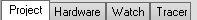
¶ Pannello Structures
Contiene pagine che includono il Project tree, Hardware tree, watch list delle variabili e Tracer.
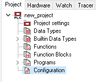
¶ Pagina Project
Nella pagina project viene mostrata la struttura del progetto. il root node è il nome del progetto, la sua sotto-entità rappresenta le parti principali del progetto. Le operazioni possibili in questa sezione sono eseguite con un doppio click o right click sui nodes.
¶ Project Settings
Doppio click per aprire una finestra pop-up con le informazioni e impostazioni del progetto. E' lo stesso pop-up dal menù Settings in Edit -> Project.
¶ Data Types
Doppio click per creare data types in modalità testuale. Un modulo text editor apparirà.

¶ Mapping Data Types
Data types creati con l'editor EDS.
¶ Builtin Data Types
System Data Types usati in alcuni Function blocks o dall'utente.
¶ Function, Function Blocks e Programs
Doppio click per esplorare le nodes structures, Right click per aggiungere POUs o cartelle.
E' possibile rinominare e cancellare cartelle all'interno di questi tre nodes. Sono un livello di cartelle è permesso. Per POUs dello stesso tipo, è possibile fare drag & drop tra le cartelle.
¶ Configurazione
Nel livello sottostante si trovano data types, POus e la configurazione conf1.
Doppio click su di esse per aprirle nel pannello editor.
¶ Pagina Hardware
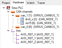
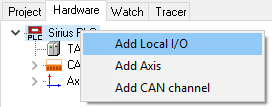
Questa è la configurazione hardware. Il root node è il PLC Sirius. Quando un progetto viene creato, l'hardware tree è vuoto (solo root).
Per aggiungere hardware, right click su rooot o node, poi premi il tipo di hardware desiderato, se la scelta è multipla apparirà una finestra pop-up per selezionare gli elementi hardware.
Local I/O rappresenta il tipo di scheda PLC Sirius. Mappa pins I/O.
I canali CAN contengono il can bus dell'hardware.
Sotto un canale CAN è possibile aggiungere CAN Nodes che erediteranno proprietà dal proprio genitore.
Axis rappresente il totale di axis. Uno o più Axes possono essere associati a una periferica.
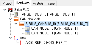
Dopo aver configurato l'hardware, il tuo tree potrebbe essere come quello mostrato sotto.
Right click sul node per mostrare il menù contestuale; poi Aggiungi, Rinomina, cancella o copia (se possibile) gli elementi selezionati. Quando il node è selezionato, premi il pulsante F2 per rinominarlo o Del per cancellarlo.
Per mostrare le proprietà hardware, doppio click su nodes per aprire la pagine "Hardware" nel pannello editor.
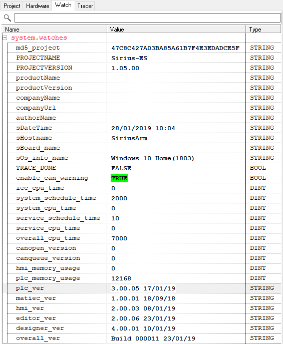
¶ Pagina Watch
La pagina watch è usata per monitorare i valori delle variabili durante l'esecuzione del programma. Questo è possibile con la simulazione del PLC o sul dispositvo reale (Connettiti al dispositivo premendo il pulsante Connect nella barra tool).
Le variabili possono essere aggiunte alla watch list dopo essersi connessi al PLC.
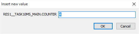
I valori possono essere modificati per cambiare il runtime dei valori del PLC; per valori booleani scrivi 0/1 o true/false o doppio click sul nome della variabile per fare toggle del valore.
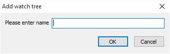
E' possibile creare gruppi per l'organizzazione delle variabili. E' anche possibile filtrare variabili dal campo di testo. Right click dentro la watch tab per aggiungere gruppi.
Poi scrivi il nome del gruppo.
Per aggiungere una variabile nel gruppo creato, selezionalo e "add" la variabile.
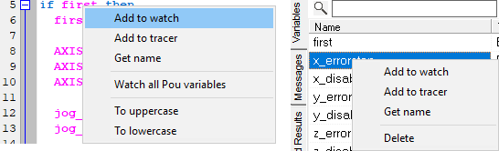
Se il dispositivo è connesso, la variabile può essere aggiunta alla watch list dal pannello Variable. Right click sul nome della variabile, poi premi "Add to watch" per allegare la variabile alla watch list. E' possibile aggiungere una variabile dal pannello editor.
Se il POU è in testo strutturato, right click sul nome della variabile e premi "Watch variable" per aggiungerla.
L'ozione "Get name" copia negli appunti il runtime full name della variabile.
"Watch all POU variables" aggiunge alla watch list tutte le variabili usate nei POU, locali o globali.
Se è un POU ladder, CTRL + Left click per aggiungere la variabile nella watch list. Quando il PLC è connesso, i valori delle variabili saranno riempiti con i valori di runtime. Puoi impostare i valori modificandol il campo "value".
Il Watching delle variabili può essere fatto in diversi formati, premi Edit menu, seleziona Show mode e cambia il formato dei valori (Decimal, Binary o Hex)(Vedi barra Menù -> Menù Edit).
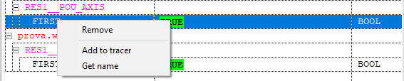
Right click sul watch list node per mostrarne il menù contestuale.
¶ Remove
Cancella la variabile, POU o gruppo dalla watch list.
¶ Add to tracer
Copia l'intero nome della variabile nel tracer, per monitorarne il valore con l'oscilloscopio.
¶ Get name
Copia l'intero come della variabile negli appunti. IE: FIRST sarà copiata come RES1__TASK10MS_MAIN.FIRST
¶ Pagina Tracer
La pagina Tracer è il monitor delle variabili e can channels.
Ci sono due pagine interne: Oscilloscope e Can-Bus.
La prima contiene un semblice data logger per monitorare le variabili. Può registrare dati delle variabili (max 10 variabili) fino a un massimo di 1000 campioni per ogni variabile.
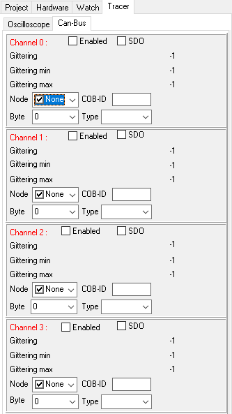
La pagina Can-Bus mostra il jittering per tutti i 4 can channels supportati.
E' possibile filtrare ogni can channel per Node ID e COB-ID per mostrare solo i dati desiderati.
I campi Byt e Type sono usati per fare il cast dei dati in un formato IEC specifico. Dal byte selezionato, gli altri byte sono visualizzati nel formato dati specificato (IE: WORD, REAL LWORD...).

¶ Oscilloscope
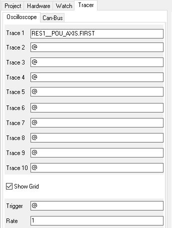
Le traccie da 1 a 10 sono spazi per le variabili da campionare. Il nome dev'essere il runtime name della variabile, come nella pagina Watch.
Show grid abilita/disabilita la barra gialla verticale sulle tracce.
Trigger è un campo booleano che può fermare la registrazione quando la variabile booleana specificata è impostata come true.
Rate è il timing di campionamento. Dice al sistema quando campionare le variabili, con multipli del Realtime timing specificati nel modulo di configurazione.
Rate * Realtime timing = Sample timing.
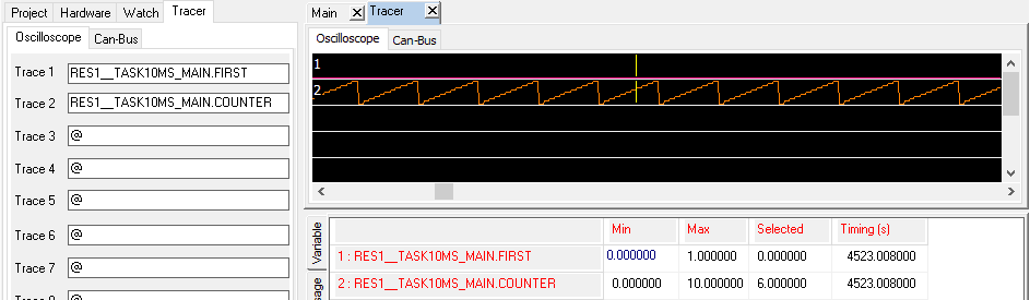
Il pulsante TRACE nella barra Tool è abilitato quando l'IEC Editor è conneso al PLC (o alla simulazione). Premendo il pulsante il sistema inizierà la registrazione, premendolo di nuovo, la fermerà e mostrerà i risultati nel modulo Tracer.
Il valore sulla destra indica il numero di millisecondi registrati.
Il modulo mostra i valori delle variabili nella registrazione campionata.
Nella pagina inferiore ci sono informazioni circa le variabili: i valori minimi e massimi sono fissi; la selezione cambia quando il cursore (barra gialla verticale) viene mosso con il mouse o con le frecce sulla tastiera. Mostra il valore sotto il cursore.
Timing è il tempo assoluto della macchina dall'ultima accensione.
Il tracer può salvare 1000 campioni per ogni variabile; dopodichè i vecchi campioni andranno persi. Il sistema registra finchè non finisce la memoria.
Usando CTRL+Rotellina, l'oscilloscopio può fare zoom in o out.
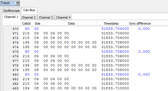
¶ Can-Bus
Questo è il monitor dei CAN channels. Mostra tutti i pacchetti mandati e ricevuti da/a i Can nodes. La Sync difference mostra il tempo in secondi da un pacchetto all'altro dello stesso tipo.
¶ Pannello Edit
Il pannello Edit contiene tutte le pagine per inserire, modificare e msotrare dati e codice sorgente. Può contenere diversi tipi di modulo, collegati al tipo di dati da mostrare o alla sezione selezionata. Il pannello Eit contiene il modulo listato di seguito:
- Hardware
- POUs
- Structured text
- Ladder
- Configuration
- Data Type
¶ Hardware
Il modulo Hardware contiene tutte le informazioni dell'hardware tree node selezionato. Doppio click sull'hardware tree node per aprirlo (vedi imamgine sotto).
La colonna InitValue è modificabile. L'utente può personalizzare l'hardware. GLi Initial values sono salvati nel progetto.
Se il node selezionato ha figli e questi hanno lo stesso campo, il valore modificato viene ereditato dai campi dei figli.
Puoi filtrare le proprietà per nome scrivendo testo nella casella di ricerca in cima alla pagina.
Quando l'IEC Editor è connesso al dispositivo o alla simulazione modificando le celle della colonna. InitValue può essere modificato solo quando si è disconnessi (dev'essere fatta la build o il make per vedere gli effetti dei valori modificati), RuntimeValue è modificabili solo quando si è connessi al PLC.
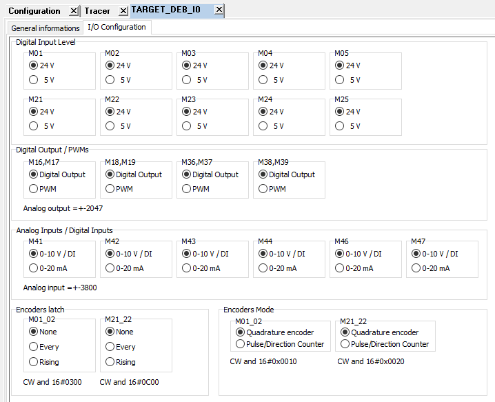
¶ Local I/O
Quando un dispositivo target è aggiunto, è possibile configurarlo facendoci doppio click sopra.
Un modulo apparirà per gestire la configurazione dei pins.
Selezione l'uso del pinout desiderato.
Per usare gli Analog inputs come digital inputs, usa i campi DI_STRUCT, per uso analogico usa i campi AI_STRUCT.
Se necessiti un analog input con corrente, solo AI_STRUCT può essere usato.
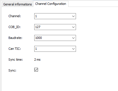
¶ CAN Channel
Permette di configurare ogni can channel.
Channel può essere 0 o 1.
Cob-id può essere specificato per ogni canale, il default è 127.
Baudrate è la velocita del canale. Scegli tra 125-250-500-1000 bps.
Can TIC è il contatore per il messagio di sync.
Dal system time (fast task) ogni Can tic viene mandato il messaggio di sync.
Sync time = System time * Can tic.
Sync enable/disable il messaggio di sync per i nodes.
Premessa:
"Il carico sul bus è troppo alto / The load on the bus is too high" ignifica che il controller fallisce la lettura/scrittura attraverso il bus, principalmente a causa di:
| Cavi non sono connessi correttamente dal client al lato server | Slot errati, il cavo non è cablato correttamente. |
| Troppi dati sono mappati, il cycle time non è sufficiente | Aumenta "CANBAUDE" aumenta "Task_System" time |
| Bad wiring or electrical noises | |
| Termination resistors del bus invalidi | Misurando dal cavo "CH" a "CL" il valore della resistenza elettrica dovrebbe essere +/- 60 ohm Un valore maggiore significa che probabilmente non c'è nessuna slave termination Un valore minore significa che probabilmente c'è più di una slave termination Cavo non è cablato correttamente. |
| ERRORRX | Uno o più TPDO mappati non è stato ricevuto Il carico sul bus è troppo alto (vedi la premessa) Il Client è mal configurato o non ha questa voce. |
| TXFQFULL | Messaggio CAN in uscita non è stato recapitato al client CAN BUS status è in "Bus Off" o in "Passive Mode" Il carico sul bus è troppo alto (vedi premessa) Il bus controller è occupato, guarda il valore di "IF_COMR_BUSY". |
| CANRXERR\CANTXERR | Il carico sul bus è troppo alto (vedi premessa) |
| CANTXERRCNT | Conta quante volte CANTXERR ha raggiunto un valore sbagliato. |
| BUS_STATUS | Bus off, problema elettrico Warning, delay flushing read/write queue Modalità passiva, cavo disconnesso Additional error infos stuff form ack, bit1, bit0, crc |
| REGISTERBUF | Contatore errore modalità passiva |
| STATUS_BOFF | Contatore errore bus off |
| STATUS_EWARN | contatore errore "warning" |
| STATUS_EPASS | Contatore errore modalità passiva |
| IF_COMR_BUSY | Il controller hardware ha problemi |
| LOST_MSG_OBJ | Qualcosa è andato storto nella ricezione dei messaggi |
| STATUS_KO | Flag al segnale che il bus presenta errori |
| TX_BUFFER_KO | Flag al segnale che ci sono errori nel flusso di dati uscente |
| RX_BUFFER_KO | Flag al segnale che ci sono errori nel flusso di dati entrante |
| QUEUE_SIZE_OUT | Dimensione reale della coda uscente |
| QUEUE_TAIL_OUT | Contatore di quante volte la coda uscente è diventata piena |
| QUEUE_SIZE_IN | Dimensione reale della coda entrante |
| QUEUE_TAIL_IN | Contatore di quante volte la coda entrante è diventata piena |
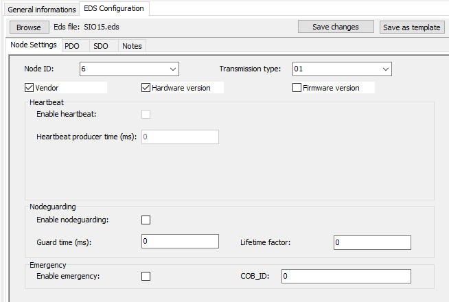
CAN Node
Se il node selezionato è un CAN node, la pagina di configurazione EDS apparirà.
La pagine di configurazione dell'EDS (electronic data sheet) permette all'utente di configurare un can node da un file eds.
Per configurare un node dall'eds, prima importa il file eds dal menù Tools -> Import eds file....
Una volta importato, premi sul pulsante "Browse" dal modulo per scegliere il file e caricarlo.
Una volta selezionato il file, il sistema carica informazioni da esso e riempe i campi con il valore di default.
Il modulo contiene quattro pagine interne, usate per configurare la node communication da/a il PLC.
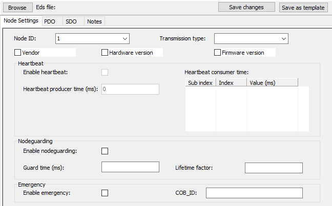
Node Settings
Questa pagina contiene informazioni generali circa la configurazione del node. I blocchi del modulo saranno abilitatise le relative sezioni sono presenti in eds file loaded.
Node ID è configurabile da questo mdoulo o dalla pagina di informazioni generali.
L'avvio controlla Vendor, Hardware e Firmware sono abilitati se il node li supporta (e il file eds contiene queste informazioni)
La combo di default transmission type contiene valori da 0 a FF; se selezionata il valore viene usato per configurare le impostazione dei PDOs.
Il sync time è calcolato con il TaskSystem Timing e il valore CanBus e CanTic. Se questo valore è vuoto il sistema userà 1 di default.
Heartbeat e Nodeguarding non sono entrambi selezionabili. Se uno è selezionato, l'altro sarà disabilitato.
Se nel file sono presenti Heartbeat consumer times, il sistema mostra la tabella consumer dove impostare ogni valore.
Emergency è abilitato se è configurato nel file eds.
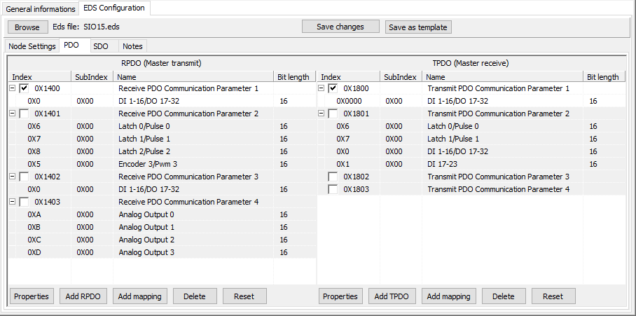
Pdo mapping
In this tab, RPDO and TPDO can be configured In questa pagina RPDO e TDPO possono essere configurati.
Il modulo presenta il mapping PDO configurato nel file caricato. E' possibile modificare il mapping, aggiungendo e eliminando oggetti dai PDO, e cambiandone le proprietà.
Spuntando il PDO sarà abilitato per il node, per disabilitare il PDO, deselezionalo.
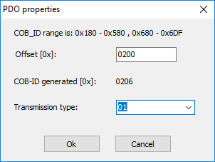
Per modificare le propietà di PDO, prima selezionalo, poi premi sul pulsante corrispondente "PDO properties" (RPDO o TDPO). Un pop-up verrà aperto per personalizzare il PDO selezionato.
E' possibile modificare il base offset in modo da generare un COB-ID con il NodeID selezionato (auto generazione del COB-ID è valida per i primi quattro RPDO / TDPO).
Il sistema può usare più di quattro PDO, se configurato correttamente.
Il transmission type viene ereditato dalla pagine Node settings, può essere modificato per ogni PDO.
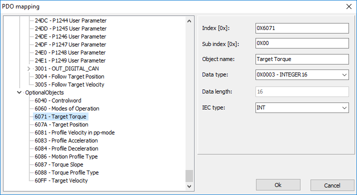
Per aggiungere un nuovo mapping, premi il pulsante corrispondente.
Una volta selezionato l'elemento corretto nel tree, premi OK per aggiungere il mapping al PDO selezionato.
Se è nessario un mapping speciale, o l'elemento desiderato non è presente, è possibile modificare l'elemento selezionato prima di premere OK. Un mapping personalizzato verrà aggiunto al PDO.
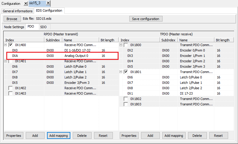
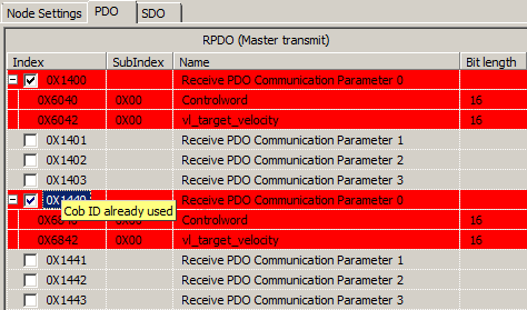
Una volta creato il mapping, apparirà nella struttura PDO. La lunghezza massima del PDO è 64 bit, se la somma delle lunghezze supera la lunghezza massima, un messaggio indicherà l'errore di configurazione.
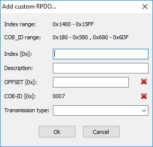
E' possibile creare RPDO/TDPO personaliizati premendo i pulsanti ADD. Un modulo appare per configurare il nuovo PDO.
Inserisci l'index, descrizione, offset per calcolare il COB-ID e il transmission type.
Per cancellare un PDO o un mapping, seleziona l'elemento e premi il pulsante "Delete" corrispondente. Se l'elemento selezionato è PDO, tutti i suoi mapping verranno cancellati.
Dopo alcune modifiche, se il risultato è un errore, è possibile resettare tutti i RPDOS / TPDOs con le configurazioni eds default. Premi il pulsante Reset corrispondente per reinizializzare i PDO.
Se si verifica un errore sui valori COB-ID, il sistema mostrerà gli errori in rosso e una finestra di informazione indicherà quale errore si è verificato.
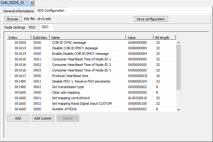
SDO
La pagina SDO contiene La lista SDO per configurare il node. Il PLC manda le informazioni SDO al CAN Node, in modo da inizializzarlo. E' possibile aggiungere un SDO direttamente alla lista, sceglierli dall'Objects Dictionary o creando un SDO manualmente.
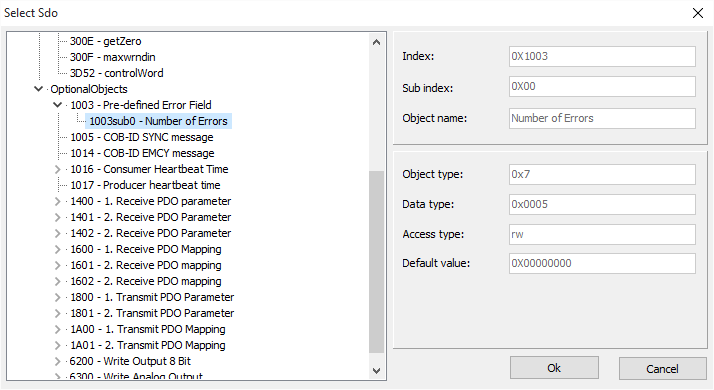
Per aggiungere un nuovo SDO premi il pulsante "Add": il pop-up dell'object dictionary permette di seleziore un elemento per aggiungerlo alla lista. Non è possibile modificare gli elementi in questo modulo.
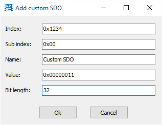
Per aggiungere un SDO personalizzato, premi il pulsante "Add custom"; con questo modulo è possibile creare un SDO e successivamente di aggiungerlo alla lista.
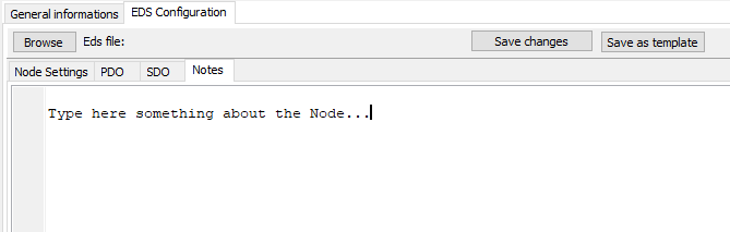
Notes
Un campo di etsto usato per prendere appunti e commenti circa il node.
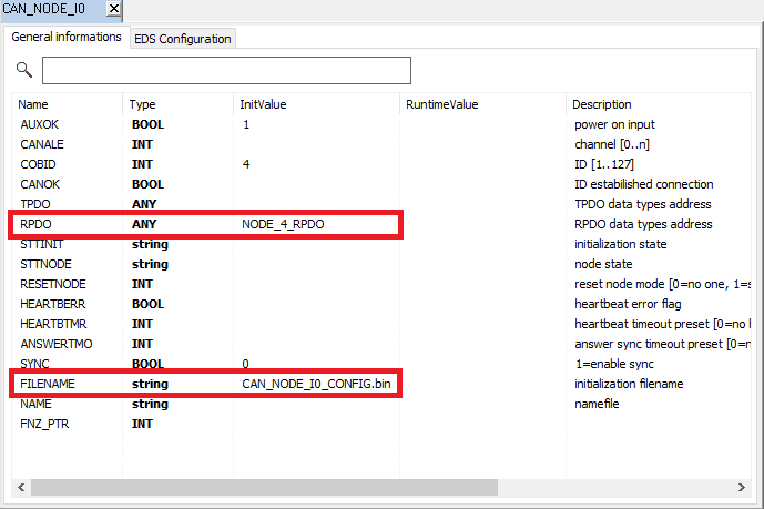
Per salvare la configurazione del node premi il pulsante "Save changes" in cima al modulo eds. Salva un file di configurazione e lo associa al node. Il nome del file è visibile nella pagina General Informations del node (FILENAME field).
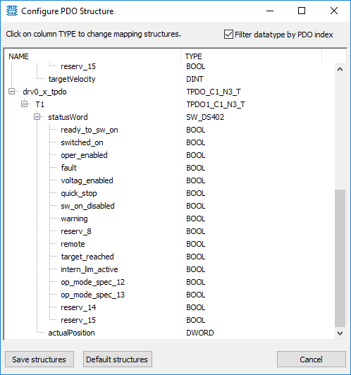
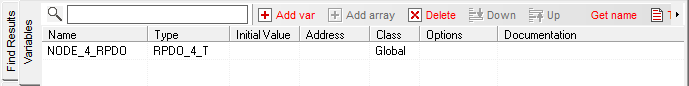
Se almeno un PDO è selezionato nella pagina PDO (e ha mapping), una finestra con le strutture data-type e variabile da creare apparirà.
Nomi e types possono essere modificati; la gerarchia della struttura verrà aggiornata con i nuovi nomi e types.
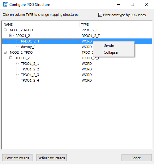
I data types possono essere divisi in due sub types (IE: una WORD può essere divisa in 2 BYTES) e due tipi uguali adiacenti possono essere uniti in uno più grande (IE: due WORD possono diventare una DWORD).
Per Dividere / unire, right click sugli elementary type nodes.
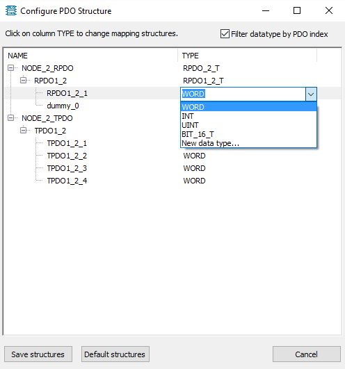
Se un Mapping node dovrebbe essere cambiato, left click su di esso e apparirà una casella combinata dove scegliere i types possibili.
Se un data-type è già stato creato per lo stesso index e bit size, apparirà nella casella.
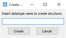
Per creare un data-type personalizzato seleziona "New data type..." dalla casella combinata.
Un pop-up permetterà all'utente di inserire il nome del data-type.
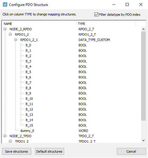
Una volta verificato il nome, la nuova struttura verrà aggiunta alla tree view dei data-types.
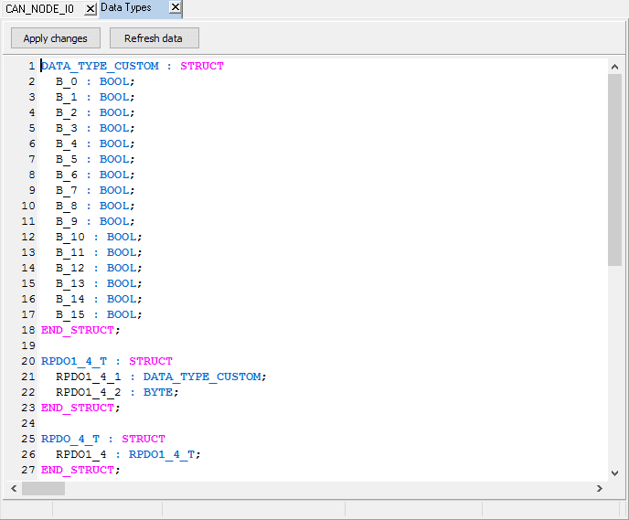
Premendo il pulsante "Save structures", il sistema creerà tutti i data-type e variabili presenti nella tree view. Se nel progetto ci sono elementi con lo stesso come, verranno sostituiti con questi nuovi elementi.
Premendo "Default structure" per resettare alla struttura proposta dal sistema.
Premi "Cancel" per annullare la creazione di strutture e configurarle manualmente. Questa operazione è molto importante e per utenti esperti.
Se la precedente struttura salvata viene modificata manualmente, il modulo Struttura proverà ad adattare i data types correnti a quella nuova.
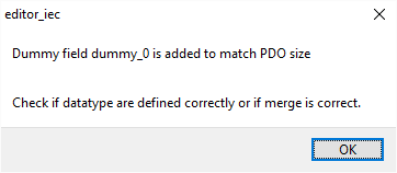
Se il numero di bytes nel data type salvato è più piccolo di quello nuovo, verranno aggiunti dei DUMMY FIELDS per riempire la nuova struttura.
Se quella salvata è più grande della nuova, i campi alla fine del data type verranno rimossi, e poi riempiti con dummy per corrispondere alla nuova struttura.
Poi la strutta unita viene mostrata. L'utente può modificarla e salvare.
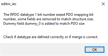
Se le variabili del node RPDO/TDPO sono già presenti, quando il pulsante Save configuration viene premuto, il sisteam caica i data-types salvati e unisce la struttura generata con essi.
Alcuni campi possono essere cancellati per uguagliare la dimensione del PDO, e alcuni campi dummy possono essere aggiunti per lo stesso motivo.
Se ci sono troppi errori nella struttura, può essere reinizializzata con il pulsante Default structure, Premendolo, la struttura sarà solo auto generata e l'utente può modificarla e salvarla.
¶ Asse
L'AXIS_REF rappresenta un asse di CNC o MOTION
Un asse ha le proprietà listate di seguito:
| ABPID | BOOL | se vera l'asse è in controllo a loop chiuso | RO |
| ABPROF | BOOL | asse in movimento o no | RO |
| ABSOFF | REAL | solo a uso interno | RO |
| ABSPOS | LREAL | posizione assoluta dell'asse | RO |
| ACC | REAL | accelerazione dell'asse UNIT/SEC" | RW |
| ACTSPA | REAL | posizione calcolata dal profile generator | RW |
| ACTSPEED | REAL | solo a uso interno | RO |
| AO_RES | REAL | risoluzione dell'output analogo | RW |
| AUXSTT | INT | solo a uso interno | RO |
| AXISIDX | INT | indice dell'asse, usato per mappare l'asse del cnc | RO |
| AXISNAME | STRING | nome dell'asse | RW |
| AXIS_ERRORID | INT | codice di errore | RO |
| AXIS_ERRORSTR | STRING | descrizione dell'errore | RO |
| COE_ENC | LREAL | unità coefficiente encoder = COE_ENC * ENCODER_PULSE | RW |
| CURRENT_FB | STRING | descrizione della macchina PLC Open state, vedi diagramma sotto | RO |
| DEC | REAL | decellerazione dell'asse UNIT/SEC2 | RW |
| DELAYPROBEOFF | INT | usato con il function block MC_HOME | RO |
| DIFPOS | LREAL | posizione derivativa sul system task | RO |
| DIRECTION | INT | solo a uso interno | RO Usato in MC_CAMIN |
| DRVOK | BOOL | stato drive esterno | RW |
| ENABLEPOSITIVE | BOOL | solo a uso interno | RO |
| ENABLENEGATIVE | BOOL | solo a uso interno | RO |
| EN_ENC | BOOL | abilita lettura encoder | RW |
| ERRDIN | REAL | errore massimo tollerato dal PID, 0 è disabilitato | RW |
| ERRPID | REAL | differenza tra ACTSPA e ASBPOS | RO |
| FCFW | BOOL | limit switch hardware premuto = true | RW |
| FCRV | BOOL | limit switch hardware premuto = true | RW |
| FKFFA | REAL | fattore derivativo del PID | RW |
| FKIA | REAL | fattore integrale del PID | RW |
| FKPA | REAL | fattore proporzionale del PID | RW |
| FLSIA | REAL | solo a uso interno | RO |
| HOMESTT | INT | solo a uso interno | RO |
| INTRATE | INT | usato per calcoli cubici, 0 = cubic disabilitato | RW |
| ISTPOS | REAL | posizione isteresi | RW |
| JERK | REAL | jerk dell'asse UNIT/SEC3 | RW |
| MAXACC | REAL | accelerazione/decelerazione massima tollerata | RW |
| MAXJERK | REAL | valore accelerazione maxjerk | RW |
| MAXSPEED | REAL | valore massimo velocità | RW |
| MODEPROF | INT | PID mode 0=feedback, 1=velocity (ERRPID non usato) | RW |
| MODULE | REAL | modulo encoder asse | RW |
| MOTION_STATE | INT | solo a uso interno | RO |
| OFSPOS | REAL | posizione offset | RO |
| OUTI | REAL | solo a uso interno | RO |
| POSFW | REAL | software limit switch 0=no software limit | RW |
| POSRV | REAL | software limit switch0=no software limit | RW |
| PROBEOFF | BOOL | usato con il blocco funzione MC_HOME | RO |
| REALSPEED | REAL | reale velocità asse UNIT/SEC | RO |
| RECVPOWER | BOOL | drive powered ON | RW |
| RECVRESET | BOOL | drive non in fault | RW |
| REF_TO_LREF | ANY | Ref to analog output variabile | RO |
| REF_TO_RAWIN | ANY | indirizzo encoder in | RW |
| REF_TO_RAWOUT | ANY | indirizzo encoder out | RW |
| RELPOS | REAL | ABSPOS + OFSPOS | RO |
| RELSIGN | BOOL | ofspos aggiunto o sottratto da abspos 0=ABSPOS\OFSPOS,1=OFSPOS\ABSPOS, | RW |
| SEGTIME | REAL | usato per calcoli cubici | RW |
| SENDPOWER | BOOL | impostato come vero da MC_POWER vedi diagramma sotto | RW |
| SENDRESET | BOOL | impostato come vero da MC_RESET | RW |
| SIMUL | BOOL | asse in simulazione | RW |
| SPEED | REAL | solo a uso interno | RO |
| STTJERK | INT | solo a uso interno | RO |
| TIMPOS | INT | posizione finale timeout | RW |
| TIMPOSOK | INT | tempo da restare in ISTPOS | RW |
| VERBOSE | SINT | verbose level 0=nessuno 1=critico 2=tutti i messaggi | RW |
| ZEROACC | REAL | usato da MC_HOME | RW |
| ZERODEC | REAL | usato da MC_HOME | RW |
| ZERODIR | BOOL | usato da MC_HOME | RW |
| ZEROED | BOOL | usato da MC_HOME | RW |
| ZEROSPEED | REAL | usato da MC_HOME | RW |
| ZEROLSPEED | REAL | usato da MC_HOME | RW |
¶ POUs
I POUs possono essere definiti in diversi linguaggi di programmazione: ST (Structured Text), Il (instruction List) e Ld (Ladder).
ST e IL sono editor testuali, LD ha specifici moduli per creare Diagrammi Ladder.
¶ Structured text
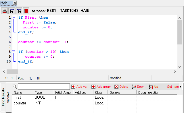
Il modulo ST è un text editor che permette all'utente di scrivere codice per programare PLC.
Il modulo contiene pulsanti per stampare la pagina e gestire risultati di ricerca (Next e Previous). Il pulsante Block apre una finestra pop-up dove inserire blocchi di codice (anche usato per programmazione LD).
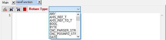
Se il POU è un programma o blocco funzione, il nome dell'istanza è visibile (lampeggio nero/rosso non riempito). Se è una funzione, il modulo mostra il suo return type.
La pagina variable mostra le variabili locali (local, in, out, inout, tempo) del POU selezionato.
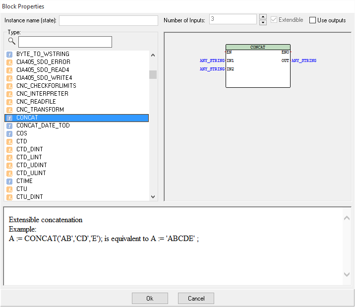
Premendo il pulsante "Insert block..." il modulo di proprietà del blocco viene mostrato.
In cima, nome dell'istanza (da riempire se l'elemento selezionato è un blocco funzione) e numero di input può essere specificato per diverse funzioni, se la funzione è estensibili e se sta usando outputs o meno.
Sulla sinistra contiene una lista di funzioni disponibili e un campo di ricerca per filtrare funzioni/blocchi di funzione e il codice di esempio.
Al centro c'è una rappresentazione grafica della funzione selezionata (usata nei diagrammi Ladder).
Sul fondo ci sono la descrizione e esempi di codice per la funzione specificata.
Dall'immagine d'esempio, la funzione Concat è selezionata, quando questo codice verrà aggiunto all'origine, assegnalo a una variabile e sostituisci il commento con i valori di input (esempio in ST)
:= CONCAT(IN1 := (*ANY_STRING*));
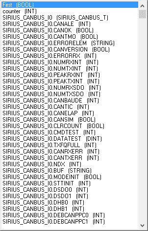
Il modulo editor ha una funzione di auto-completamento: premi CTRL+SPACE per aprire una finestra contestuale dove scegliere le variabili; scrivendo dei caratteri, il contenuto del pop-up verrà filtrato automaticamente.
CTRL+Rotellina dela mouse per fare zoom in e out.
Quando si è connessi al PLC, è possibile cambiare i valori delle variabili direttamente dal modulo editor.
CTRL+Doppio click, fa il toggle dei valori se la variable è booleana, o mostra un pop-up per inserire il nuovo valore.
¶ Ladder
Il Ladder Diagram è un linguaggio di programmazione su base grafica che semplifica e approssima la struttura di un circuito elettrico.
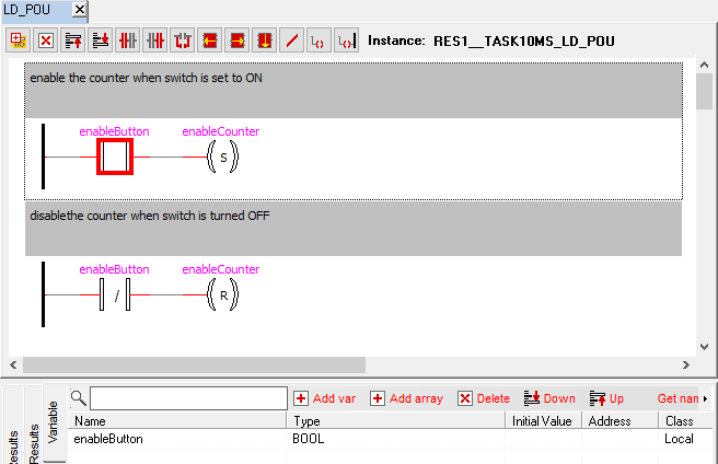
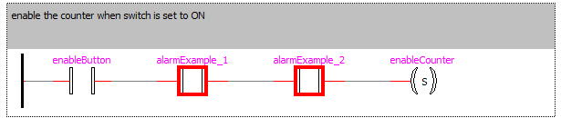
Il Ladder Diagram consiste in una serie di networks, ognuno delimitato da una linea di corrente verticale (power rail) sulla sinistra. Ogni network contiene un circuit diagram formato da contatti, bobine, POUs addizionali opzionalmente (boxes) e linee di collegamento. Sul lato sinistro c'è uno o una serie di contatti che passano da sinistra a destra la condizione "ON" o "OFF" che corrisponde ai valori booleani "TRUE" o "FALSE". Ad ogni contatto viene assegnata una variabile Booleana. Se questa variabile è TRUE, la condizione verrà passata da sinistra a destra sulla linea di collegamento. In caso contrario, "FALSE" passerà. Dunque le bobine, che vengono posizionate nella lato destro del network, ricevono un segnale "ON" o "OFF" da sinistra e il valore "TRUE" o "FALSE" verrà scritto nelle variabili booleane assegnate.
Clicca il pulsante "New rung" [F2] per aggiungere un nuovo diagram block.
Il pulsante "Delete selected item" [F3] cancella il componenete selezionato (cancella il rung corrente se non è selezionato nessun componente).
I pulsanti "Move up/down rung" [CTRL+PGUP] [CTRL+PGDN] cambiano l'ordine dei rung, muovendo quello corrente sopra o sotto nell'ordine del modulo.
Nei rung blocks, si possono posizionare i contatti premendo i pulsanti Serial (sinistra o destra) o Parallel [F3 .. F5].
Per aggiungere funzioni o function blocks, premi il pulsante blocks (seriale sinistra, destra o parallela) [F6 .. F8]. Il modo di proprietà del block apparirà: scegli la funzione desiderata.
Il pulsante "Negate" [F9] inverte la codizione logica di un contatto/bobina.
Il pulsante "Break" [F10] crea una fine alternativa per il rung a sinistra dell'elemento selezionato (aggiunge una bobina).
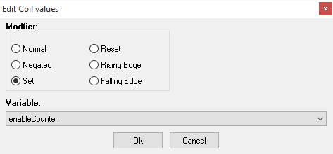
Il pulsante "Add coil" [F11] aggiunge una bobina in parallelo alla fine della linea.
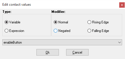
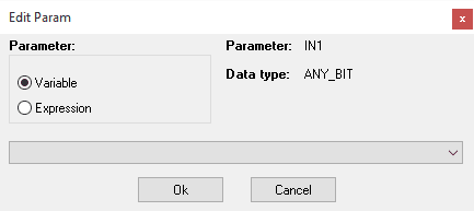
Per modificare contatti, function blocks, variable blocks e bobine fai doppio click su di essi.
Nei contatti, il valore può essere preso da variabili o da espressione Structured Text (che restituisce vero o falso).
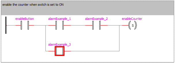
Per aggiungere un contatto/block in parallelo su una serie di diversi componenti, selezioni i componenti di cui hai bisogno (Shift sx + Left Click) e poi premi il pulsante parallel.
La dichiarazione delle variabili è la stessa dell'altro editor.
Per modificare le variabili input/output dei Blocks, doppio click su IN o OUT del block (o doppio click sul nome della variabile)

Per
Per aggiungere un contatto/block in parallelo su una serie di diversi componenti, selezioni i componenti di cui hai bisogno (Shift sx + Left Click) e poi premi il pulsante parallel (Parallel contact [F5] or Parallel Block [F8]).
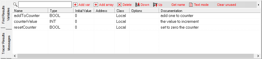
Figure 2.70 Diverse selezioni per parallel+
E' possibile lavorare nell'editor LD con alcune shortcut per la tastiera. Di seguito le funzioni di ogni tasto:
| Tasto | Funzione |
|---|---|
| RETURN | Modifica il contatto, bobina o block selezionato |
| DEL | Cancella gli elementi selezionati o il rung |
| F2 | Crea un nuovo rung |
| F3 | Aggiungi un contatto in serie a sinistra |
| F4 | Aggiungi un contatto in serie a destra |
| F5 | Aggiungi un contatto in parallelo |
| F6 | Aggiungi un function / function block in serie a sinistra (apre la finestra delle proprietà Block) |
| F7 | Aggiungi un function / function block in serie a destra (apre la finestra delle proprietà Block) |
| F8 | Aggiunge un function / function block in parallelo (apre la finestra delle proprietà Block) |
| F9 | Nega il contatto o bobina |
| F10 | Aggiunge un bobina break |
| F11 | Aggiunge una bobina |
| CTRL + C | Copia rung negli appunti |
| CTRL + X | Taglia rung |
| CTRL + V | Incolla rung dagli appunti |
| CRTL + S | Salva progetto |
| ↑ ←↓→ |
Muove la selezione all'interno del rung |
| CTRL + ↑ | Muove la selezione all'interno dell'input-output di una function |
| CTRL + ↓ | Muove la selezione all'interno dell'input-output di una function |
| CRTL + RETURN | Modifica il Variable block selezionato (IN o OUT) |
| PG ↑ | Seleziona il rung precedente |
| PG ↓ | Seleziona il rung successivo |
| CRTL + PG ↑ | Muove il rung selezionato in alto |
| CRTL + PG ↓ | Muove il rung selezionato in basso |
| CTRL + Click left | Add to watch variable |
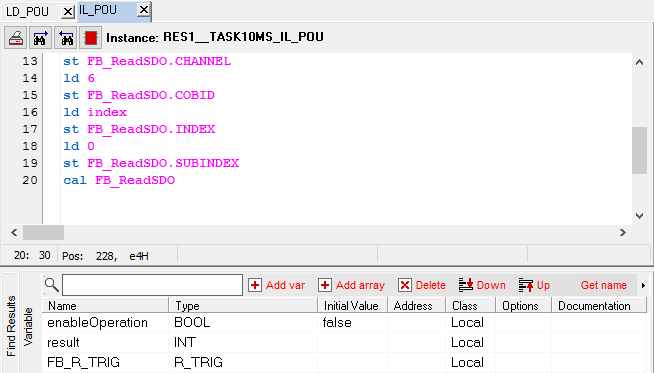
¶ Instruction List
Instruction List (IL) è un linguaggio di programmazione testuale simile al linguaggio assembly. Il codice IL consiste in una sequenza di istruzioni separate da linee, che consistono in un operatore (COMMAND", un operando (variabile, costante o nome dell'istanza) e un modificatore opzionale rispettivamente. Possono essere usati jumps ed etichette.
IL usa le stesse regole di editor dei POUs ST, con keywords differenti e highlighting.
La dichiarazione delle variabili è la stessa dell'altro editor.
¶ Configuration
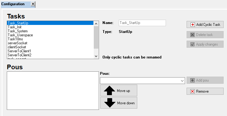
La pagina configuration permette di creare tasks e le loro istanze.
Ci sono quattro tipi di Task: INIT, STARTUP, SYSTEM, CYCLIC e USERSPACE.
Per avviare un POU, dev'essere aggiunto a una task.
¶ Tasks
Il modulo di configurazione definisce una o più task per controllare il processing di un application program.
Per creare una nuova task inserisci il nome, type e timing (se abilitato); poi premi add.
Premi delete per cancellare la Task selezionata.
Seleziona un task, modificala per cambiarne le proprietà, poi premi apply per salvare la task modificata.
CI sono quattro tipi di trask mostrati nella tabella sottostante:
| Task Type | Funzione |
|---|---|
| Init | Chiamata una volta alla partenza del programma, usata per avviare i POUs di setup. |
| StartUp | Dopo le Init tasks, il sistema configura l'hardware (assi, can nodes) Quando l'hardware è configurato la StartUp task viene cambiata per fare il setup del sistema (o del programma) con l'hardware corretto. Ie: ID degli assi o can nodes inizializzati. |
| System | Tasks in tempo reale. Sono task deterministiche e funzionano in un real time engine. Il time cycle è definito nel "Real time cycle time text box" |
| Userspace (Slow) |
Task con la priorità più bassa, chiamate ogni 50 ms se possibile (tempo minimo). |
| Cyclic | CLe cyclic tasks sono usate per avviare programmi, NON sono deterministiche e il tempo può essere più lento; dipende dal carico di lavoro. Il tempo è inserito dall'utente e dev'essere maggiore e multiplo del tempo Real-time. |
La Real-TIme Cycle time TextBox è usata per impostare il real time timing. I valori devono essere nel formato: T#xxxD xxxH xxxM xxxS xxxMS (D = days, H = hours, M = minutes, S = seconds, MS = milliseconds). Il valore minimo di tempo è 1ms.
Il tempo delle cyclic tasks dev'essere superiore del tempo delle Real-time tasks in modo da leggere/scrivere i valori delle variabili del PLC aggiornati.
¶ Instanze
Le istanze sono la rappresentazione di un programma che funziona in tasks specifiche. Per creare una nuova istanza, seleziona tasks, e seleziona il programma da avviare; poi premi "add POU".
Quando il progetto è avviato, i POU sono eseguiti con il timing selezionato. Le istanze Real-time hanno la priorità superiore, le istanze Slow quella inferiore.
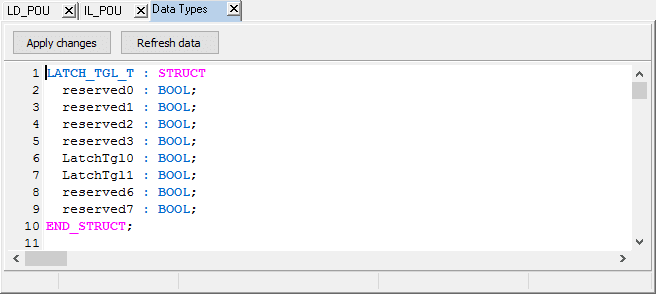
¶ Data Types
I Data Type (o strutture) sono entità che descrivono un gruppo di basi data types (come BOOL o INT).
I Data type non possono contenere function blocks o array.
I Data type possono essere definiti dall'utente, doppio click sul nodo "Data Types" nel project tree (o doppio click sul data type creato) per aprire l'editor.
¶ Data Types editor
E' un semplice editor di testo usato per creare data type. Le keywords sono evidenziate per aiutare l'utente nella scrittura del codice. Dopo aver inserito il codice, premi "Applica cambiamenti" o "CTRL+S" per modificare i data type del progetto.
Per cancellare un data type, cancella il testo nell'editor e salva.
Per annullare modifiche o ricaricare data types, premi il pulsante "Refresh data".
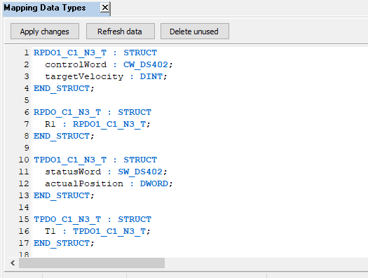
¶ Mapping Data Types
I Mapping Data Types sono le strutture create dal tool di configrazione Can Node, usando il file eds. Sono identici ai normali data type ma sono usati per la comunicazione tra PLC e Can nodes. Possono essere modificati manualmente, o con la Can Node Configuration.
L'editor di questo gruppo di data type è simile all'altro data type editor, questo però contiene il pulsante "Delete unused" per rimuovere data types senza un can node associato.
Se cambi qualcosa nella mapped structure ricorda di aprire il relativo can node con il configuratore e premi il pulsante "Save changes", in modo da rigenerare la lista sdo e la node configuration.
¶ Built in Data Types
Questi data type sono definiti dal sistema. Possono essere usati dall'utente ma non modificati. L'editor è in modalità sola-lettura.
¶ Pannello Footer
Il pannello footer contiene quattro pagine.
La pagine Variables consente la gestione delle variabili.
La pagine Message mostra i messaggi di output del sistema.
La pagina Find results contiene una lista di righe che corrispondono ai criteri di find.
La pagina Tracer mostra i valori delle variabili nel tempo.
¶ Pagina Variables
Le variabili possono essere definite in questa pagina. Ci sono due modi per dichiarare variabili, in modalità Table con finestre guidate, o in modalità testuale scrivendo codice.
Questa pagina è visibile solo se il Configuration Form o l'Editor (ST, LD o IL) è visibile. In caso contrario, questa pagina è inutilizzata.

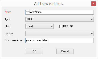
In modalità Table, per aggiungere una variabile, premi il pulsante "ADD VAR": apparirà una finestra dove una singola variabile può essere dichiarata. Gli utenti devono inserire nome, type e class. Opzionalmente è possibile specificare se si tratta di RETAIN o meno e aggiungere documentazione.
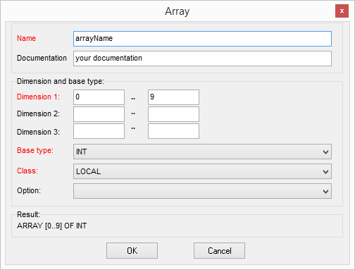
Per creare un Array premi il pulsante "ADD ARRAY", un modulo verrà mostrato per crearlo. In questo modo gli array sono tridimensionali come minimo.


Per cancellare una variabile selezionala e premi il pulsante DELETE.
I pulsanti UP e DOWN sono usati per cambiare l'ordine delle variabili, per avere una visualizzazione personalizzara delle variabili.
Il pulsante "Get name" copia il nome completo della variabile negli appunti.
Per cambiare i dati della variabile premi sulla colonna interessata e modificali.
Per cambiare la modalità di dichiarazione delle variabili, premi il pulsante Text mode per mostrare il pannello editor delle variabili.
Il pulsante "Clear unused", rimuove tutte le variabili dichiarate ma non usate nei POUs.

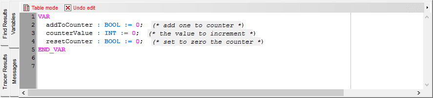
In modalità text, la dichiarazione delle variabili viene fatta in ST. Per salvare il testo, premi il pulsante Table mode per tornare alla modalità precedente.
Prima di cambiare pannello, le variabili vengono analizzate e se non si verifica nessun errore, vengono salvate nella struttura POU. Per cambiare modalità senza applicare le modifiche, premi il pulsante Undo edit.
In modalità text le variabili possono essere dichiarate come nell'esempio seguente (il testo in {} è opzionale):
VAR
  varName {AT %ADDRESS} : varType {:= varInitialValue}; {(* varDocumentation *)}
  arrayName {at %ADDRESS} : array [arrayBeginIndex .. arrayEndIndex] of arrayType; {(* arrayDocumentation *)}
END_VAR
In modalità text le dimensioni degli array non sono limitate a tre come in modalità table. I valori iniziali degli array non sono supportati.
¶ Pagina Message
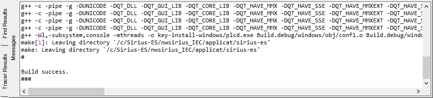
Mostra tutti i messaggi dal sistema.
Questa pagina è usata per building di errori e output, sync con il target.

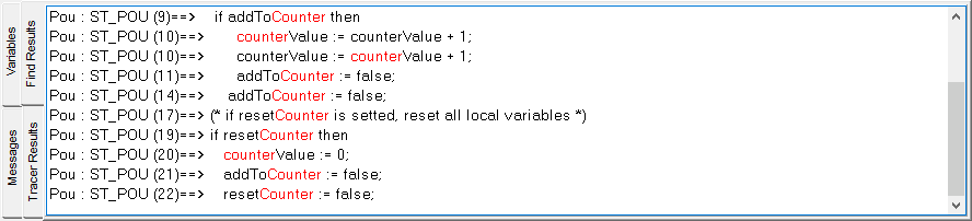
¶ Pagina Find results
Dopo aver usato le funzioni di find, tutti i risultati corrispondenti vengono elencati qui. Questa pagine indica all'utente dove è situata la stringa ricercata: Configuration (variabile globale), Data Type o POU. Nel caso del POU, il nome e le righe sono specificati.
Doppio click su una riga per andare al codice sorgente nel modulo editor.

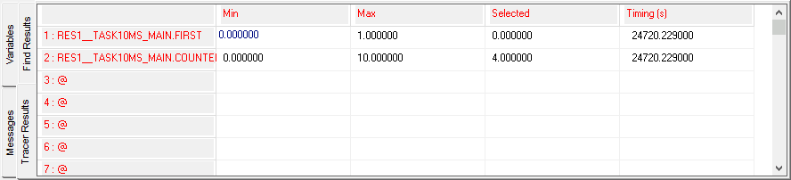
¶ Pagina Tracer results
La pagina Tracer results funziona con l'Oscilloscope e mostra i valori delle variabili nel tempo. Valori minimi e massimi raggiunti sono listati nella tabella con il loro valore reale. Questo campo cambia quando l'utente muove il cursore sull'oscilloscopio, La colonna timing rappresentea il tempo trascorso (dal boot del dispositivo) in secondi del campione.

¶ Pannello Debug
Il pannello di debug consente all'utente di fare debug in simulazione o sul dispositivo.
// TO BE DEFINED