¶ Indice
- Download
- Informazioni generali
- Interfaccia utente
- Oscilloscope
- Code editor
- Logger
- ST Programming Reference
- IEC Building procedure
¶ 0. Download
L'ultima versione è la 2.33 Sirius Device Manager.exe
L'ultima versione del device manager con ambiente di compilazione è la 01.23.01 delivery-01_23_01.zip
Attenzione: è necessario che il percorso dove si scarica device manager sia senza spazi e senza punti.
¶ 1. Informazioni generali
Sirius Device Manager è il software usato per gestire le configurazioni hardware, lo sviluppo e il test.
Con questo tool l'utente può:
-
Generare configurazioni per ogni dispositivo e salvarle.
-
Caricare configurazioni salvate dal PC al dispositivo.
-
Monitorare le operazioni del dispositivo.
-
Analizzare le variabili.
-
Calibrare il dispositivo.
-
Sviluppare codice IEC da caricare sul dipositivo.
¶ Richieste di sistema
-
Sistema operativo: Windows 7 o superiore con architettura 32/64 bit.
-
Porta USB disponibile.
-
RAM: 512MB
-
Disk space:
- 10 Mb (SOLO DEVICE MANAGER)
- 600 Mb per la versione IEC
-
Cavo USB a Seriale (FDTI).
¶ 2. Interfaccia utente
L'interfaccia utente consiste in tre pagine principali:
- Oscilloscope
- Code editor (per la versione IEC)
- Logger
¶ Menù File
Menù per caricare e salvare dati.
| Load serie setup | Carica una serie salvata precedentemente, in modo da impostare il sistema. |
| Save serie setup | Salva la serie di variabili, in modo da avere dei setup salvati. |
| Load graph | Carica le tracce delle variabili salvate. Con questo è possibile analizzare i dati offline. |
| Save graph | Salva le tracce delle variabili selezioni, in modo da navigare i dati offline. |
| Export graph in to... | Esporta le variabili selezionate in formato CSV, per analizzare i dati con altri programmi. |
¶ Menu Options
| Reboot device | Manda il comando REBOOT al dispositivo. |
| Switch target | Comando per una piattaforma hardwware specifica, comunica al master target quale slave dev'essere connesso. |
| Take screenshot | Crea una foto dello schermo del Device manager, per catturare uno stato particolare. |
¶ Menu Help
| Help online... | Questo sito. |
| Help contextual... | Mostra l'aiuto contestuale alla variabile selezionata |
| About | Mostra un pop-up con le versioni del software. |
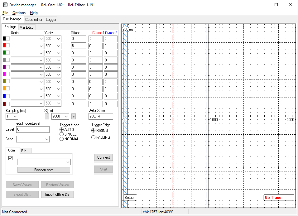
¶ 3. Oscilloscope
La pagina Oscilloscope contiene i tools per gestire i dispositivi SIRIUS-ES.
Consiste in tre parti:
- Pagina Settings
- Pagina Var Editor
- Charts panel
¶ Settings
La pagina Settings contiene i controli per monitorare, salvare e recuperare i valori da/a i dispositivi.
Può essere divisa in tre parti:
- Variables monitor (oscilloscopio)
- Connect to hardware
- Save/Restore values
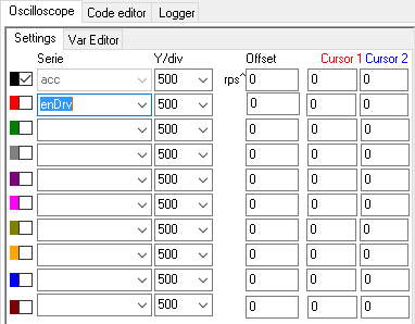
¶ Variables monitor
Questa parte della pagine è usata per monitorare le variabili nel Charts panel.
La prima colonna (color and checkbox) rappresenta il colore della traccia. La checkbox indica al sistema se la variabile dev'essere mostrata o meno in modo da caricare un set di serie e mostrare solo quelle selezionate.
La variabile può essere selezionata nelle caselle combinate "Serie" con specifici parametri di visualizzazione.
La colonna Y/div indica al Charts panel il numero di punti per ogni blocco.
La colonna Offset imposta l'offset dell'oscilloscopio.
Le colonne Cursor 1 e Cursor 2 mostrano i valori numerici sotto i due cursori dell'oscilloscopio.
Se la variabile ha un'unità di misura, verrà mostrata accanto alla colonna Y/div.
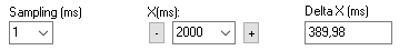
Sotto serie si trovano le impostazioni di display per il Charts panel.
- Sampling time (da 1 a 0.05 ms) che dipende dal tipo di hardware connesso.
- X (ms) division (da 10 a 5000).
- Delta X (ms) - il tempo tra i due cursori.
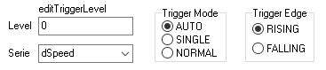
- Il trigger può essere impostato dall sezione trigger
- Level è il valore che attiva il trigger
- Serie è la variabile da guardare
- Trigger mode:
- AUTO senza trigger
- SINGLE mostra solo il primo evento di trigger
- NORMAL mostra tutti gli eventi di trigger
- Trigger edge:
- RISING il valore è diventato maggiore del valore di trigger
- FALLING il valore è diventato minore del valore di trigger
¶ Connect to hardware
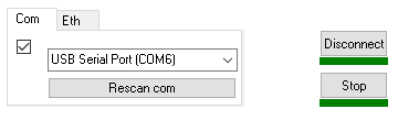
Questa sezione permette all'utente di gestire la connessione ai dispositivi. Le connessioni possono essere di due tipi: serial o network.
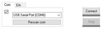
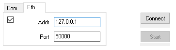
Il pulsante Connect è usato per aprire la connessione con il dispositivo.
Una volta connesso, il pulsante Connect verrà sostituito dal pulsante Disconnect.
Il pulsante Start fa partire l'oscilloscopio per mostrare i grafici.
Una volta connesso il pulsante Start verrà sostituito dal pulsante Stop per fermare i grafici.
Le line sotto i pulsanti ne indicano lo stato (verde o rosso).
¶ Save/Restore values
I pulsanti in questa sezione permettono all'utente di gestire i dati offline.
Il pulsante Save Values salva in un file le variabili retain, per creare un setup per il dispositivo connesso.
Il pulsante Restore Values manda al dispositivo le variabili retain salvate nel file.
Il pulsante Export Db salva la struttura variabile della pagina Var Editor. Può essere ricaricata in modo da funzionare offline o per sviluppare il programma IEC con il Code Editor
Una volta connesso all'hardware, una copia della struttura Var Editor viene salvata in un file.
Con il pulsante Import offline DB l'utente può caricare un set di variabili con tutti i valori di un particolare hardware, in modo da mostrarne lo stato o usare le variabile nel Code Editor.
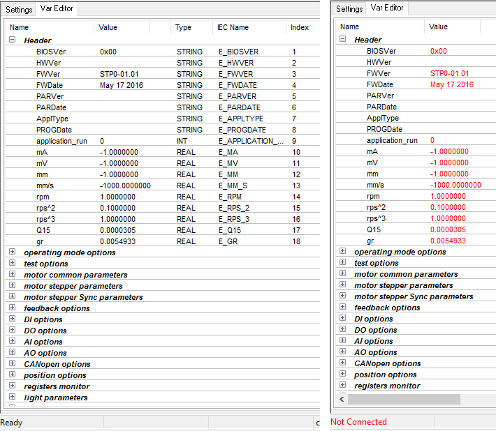
¶ Vars Editor
Contiene tutte le variabili caricate dal dispositivo.
Le variabili sono divise in gruppi (in grassetto).
La tabella delle variabili ha le seguenti colonne:
| Name | Nome della variabile |
| Value | Valore della variabile |
| U.M. | Unità di misura |
| Type | Tipo IEC della variabile (IEC version) |
| IEC name | Nome per la IEC_TAS (IEC version) |
| Index | Indice del database della variabile (IEC version) |
Il valore, una volta connesso al dispositivo può essere modificato e aggiornato in modo da vedere il runtime o salvare un nuovo valore.
I valori possono essere mostrati graficamente sui Charts panel per vederne l'andamento nel tempo.
Il database delle variabili può essere online aggiornato ogni ms via USB dal dispositivo, o offline caricato dal file.
Se è caricato dal file o l'hardware è disconnesso, le colonne dei valori diventano rosse e disabilitate.
Facendo tasto destro du una variabile verrà mostrato un menù contestuale.
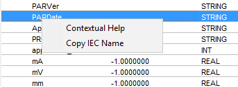
| Contextual Help | Apri l'aiuto online per la variabile selezionata. |
| Copy IEC name | Copia negli appunti il valore della colonna IEC Name. E' d'aiuto per il Code Editor quando l'utente deve digitare le variabili del dispositivo. |
¶ Charts panel
This area is used for graphical representation in time. It is the same of a oscilloscope display.
Quest'area viene usata per rappresentazioni grafiche nel tempo. E' simile al display di un oscilloscopio.
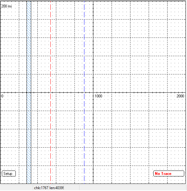
Le linee verticali rosse e blu sono i cursori dell'oscilloscopio, muovendoli i valori nei cursori 1 e 2 cambieranno.
Il rettangolo blu è l'area del crafico da ingrandire. Può essere ridimensionata con il mouse.
Right click into the area will show the zoom panel.
Premendo il tasto destro nell'area verrà mostrato lo zoom panel.
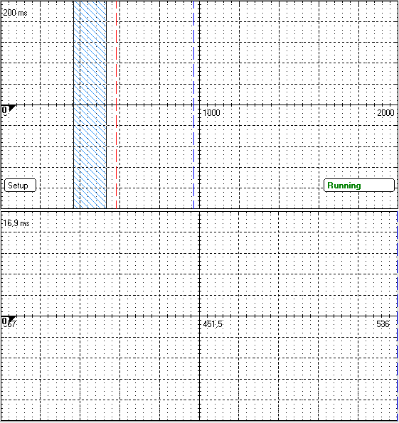
Lo zoom panel mostra i grafici all'interno dell'area blu.
Premendo il pulsante Setup apparirà un menù pop-up: contiene le impostazione di Trigger e aspetto.
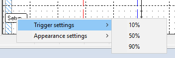
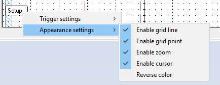
trigger settings è usato per la posizione x del trigger sullo schermo.
0% è il lato sinistro del chart panel. 100% è quello destro.
Appearance settings è usato per cambiare il layout del grafico. Seleziona o deseleziona le proprietà che desideri.
¶ 4. Code editor
La pagina Code editor contiene un editor di testo che permette all'utente di scrivere il proprio codice in Structured Text.
E' uno dei linguaggi di programmazione IEC 61131.
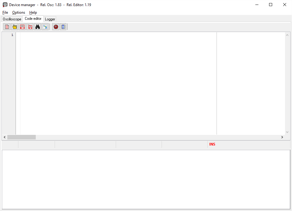
It contains the Toolbar, the text editor and the message box.
Contiene la Toolbar, l'editor di testo e la casella dei messaggi.
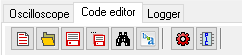
¶ Toolbar
La toolbar contiene tutti pulsanti per creare, buildare e caricare i tuoi progetti nei dispositivi.
| New... | CTRL + N | Crea un nuovo progetto. Un template verrà caricato. I template sono salvati nella cartella ./templates nella cartella root di Device Manager. Se è necessario un template differente, rinomina il template custom in template.st.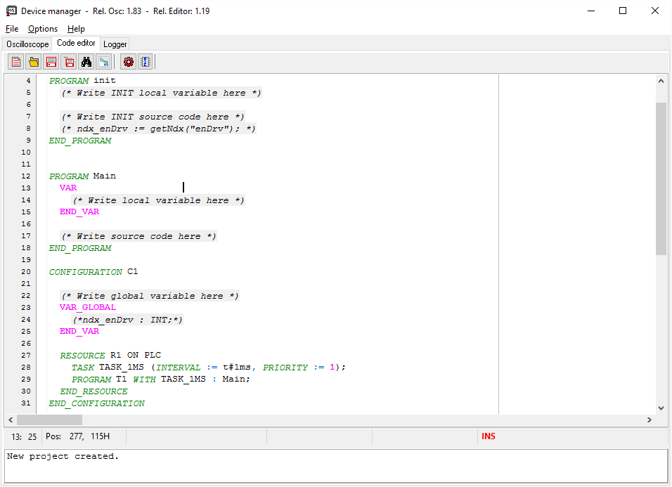 |
| Open... | CTRL + O | Apre un progetto salvato. La cartella defaul è ./project nella cartella root di Device Manager. Un form aperto viene mostrato. Solo file .st possono essere caricati. |
| Save... | CTRL + S | Salva il project file nella directory default. La prima volta un modulo di salvataggio viene mostrato per selezionare il nome del file. |
| Save as... | CTRL + SHIFT + S | Salva il project file con un nome diverso. Un modulo di salvataggio viene mostrato per selezionare il nome del file. |
| Find... | CTRL + F | Trova testo nell'editor. Un pop-up viene mostrato per iniziare il processo di ricerca.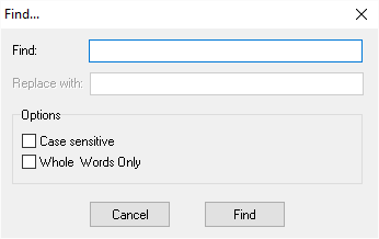 Il pulsante F3 evidenzierà la prossima apparizione del testo. SHIFT + F3 evidenzia la precedente apparizione. |
| Replace... | CTRL + R | Sostituisce testo nell'editor. Un pop-up viene mostrato per iniziare il processo di sostituzione.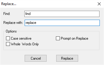 Di default sostituisce ogni apparizione del testo, per scegliere quale rimuovere e quale no, seleziona Prompt on Replace. |
| Build | Builda il project file e genera un file .bin da caricare nel dispositivo. L'output viene indicato nella casella dei messaggi sul fondo del Code Editor. |
|
| Upload Firmware... | Inizia il processo di upload del file binario sul dispositivo. Una barra di progresso apparirà per mostrare lo stato dell'upload. . Cliccando il pulsante cancel, il processo di upload sarà interrotto. |
¶ Text editor
Un semplice editor di testo per creare il progetto IEC.
Le evidenziature potrebbero aiutare gli utenti a scrivere il codice.
L'intero programma dev'essere scritto qui.
La barra di stato mostra la posizione del cursore (fila, colonne, char number) e altre informazioni circa il codice.
¶ Message box
Tutti i messaggi di sistema come le operazioni sul file di progetto sono mostrati qui.
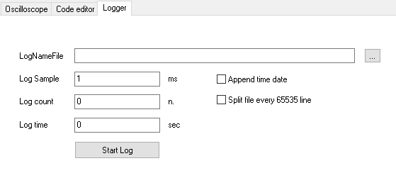
¶ 5. Logger
Questa pagina è usata per registrare i valori delle variaboli.
Ogni variabile spuntata nella pagina Settings serie viene scritta nella riga specifica.
L'utente può impostare il tempo di campionamento per il logging, aggiungere data e ora a file e colonne e scegliere se dividere o meno il file.
Il log count e il log time sono aggiornati in tempo nel sistema quando l'utente preme il pulsante Start Log. Il formato del file è CSV.
¶ 6. ST Programming Reference
Vedi la pagina Sirius-ES Editor IEC:
¶ 7. IEC Building procedure
Vedi il link: